Sonoff Relays With OpenHab And Tasmota Firmware
Caution
This page has been updated a long time ago. Information found here could be outdated and may lead to missconfiguration.
Some of the links and references may be broken or lead to non existing pages.
Please use this docs carefully. Most of the information here now is only for reference or example!
TL;DR
I'm using OpenHab to control some Lights and equipment in my house and garden. I used to develop my own circuits using ESPs, relays, power supplies etc., but some months ago I found the Sonoff products, which offer the same or more functions than my own devices. Just for comparison here is my 4ch relay with ESP07:
And the 4CH relay from Sonoff:
However, all my own relays and sensors work fine, I had to develop a firmware for them. Since I'm not a not developer it was a big challenge for me, even with the LUA FW. So I decided to order some Sonoff products and tried them.
For the very first time I tried with its factory firmware, but it has a lot of limitations:
- It cannot be used with OpenHab. This is a show stopper disadvantage for me.
- It has no web interface.
- Very limited scheduler. (No sunset / sunrise option, etc)
- Scenes cannot be shared.
- Uses the sonoff own cloud infrastructure. That's why nobody knows what kind of information is sent to the sonoff servers. (The big brother is always watching you. :) )
I started Googling and found the Tasmota firmware easily, which is for Sonoff products. It is available on Github: Sonoff-Tasmota
There are a lot of excellent articles on the Internet which are about How to update your sonoff product with Tasmota firmware, so mine is something like "Yet, another article about...." :)
So, you need:
- One supported sonoff product. (You can find the supported device list on the official Tasmota Github page.)
- 4 solder-able pins. (For GND, RxD, TxD and Vcc)
- Soldering Station. (And willingness to solder of course.)
- USB to TTL converter.
- A PC or notebook.
- Screwdriver.
Before we start, let's say some words about Sonoffs. I'v ordered 4 different types of relays: S2 smart Socket, POW (One ch relay with power monitoring capability), Sonoff basic and Sonoff 4ch. All of them are working perfectly with Tasmota. You can visit the sonoff store on Aliexpress and I bet you will be surprised at how cheap these things are. At the moment the cheapest relay is the sonoff basic, it costs only 5$, and you can get a full system for switching things around your house, garden, holiday house even if you are far away. What about the quality? So-so. For this price I think the quality is acceptable, but not the best. For example the product sheet of the Basic says that the maximum load is 2200W. Seeing the soldering inside the cover I don't think it can bear 2.2kW. But from the other hand there is not a lot of equipment which we want to control over the internet and consumes 2.2kW. In my case I want to control some lights, fans and my water pump with these relays, so sonoff relays are perfectly suitable for my goal.
1. Soldering
As I wrote above I have 4 types of Sonoff relays. Thanks to God the most expensive one (4ch) have pre-soldered pins on it. Helpful links:
Please be aware (4ch) that "The printed labels on the PCB for Rx and Tx are incorrectly swapped as can be seen on the image."
1.1. Sonoff POW
1.2. Sonoff S20 (Socket)
1.3. Basic
The GPIO14 can be used for example to connect DHT22 sensor (or any other sensor supported by Tasmota) to the sonoff. I will assist you later how to configure Tasmota to be able to use additional sensor.
The button on sonoffs are always connected to GPIO0, except when the board has more then one button (eg.: 4ch), in this case the 1st button is connected to GPIO0.
2. Upload The Firmware
To be honest this is the easiest step.
Danger
Do not connect AC power and the serial connection at the same time!
Connection Matrix:
In order to put your device into FW upgrade mode, press and hold the button on it while connecting to VCC. You can connect all the wires and press the button when you connect the USB2TTL to your computer, or leave the VCC (only the vcc) disconnected, connect the USB2TTL to the computer, press and hold the button and connect the VCC.
Useful links:
- upgrading-sonoff-stock-firmware-to-sonoff-tasmota-usb-to-serial-and-ota-update-methods
- https://github.com/arendst/Sonoff-Tasmota/wiki/Esptool
2.1. (Optional) Take Backup
Taking backup is always optional, but essential. If you skip this step, you lose the possibility to restore the factory firmware. (It is not 100% true because I will make the stock firmware available here.)
You will need Esptool to achieve this step. If you don't know how to install it, please take a look at this page: esptool For Windows users maybe the "ESP8266Flasher" could be an option (nodemcu-flasher).
esptool.py v2.3.1
Connecting....
Detecting chip type... ESP8266
Chip is ESP8266EX
Features: WiFi
Uploading stub...
Running stub...
Stub running...
1048576 (100 %)
1048576 (100 %)
Read 1048576 bytes at 0x0 in 94.9 seconds (88.4 kbit/s)...
Hard resetting via RTS pin...
Please be aware that after any esptool command you have to reconnect to the device. (So, you have to disconnect vcc, press and hold the button and connect VCC again.)
2.2. (Optional) Erase Flash
This step is also optional, but recommended.
esptool.py v2.3.1
Connecting....
Detecting chip type... ESP8266
Chip is ESP8266EX
Features: WiFi
Uploading stub...
Running stub...
Stub running...
Erasing flash (this may take a while)...
Chip erase completed successfully in 3.2s
Hard resetting via RTS pin...
2.3. Flashing The Firmware
Till this step I haven't mentioned the firmware itself. How can you download the pre-compiled firmware? You don't need to compile the firmware, it can be downloaded from github: releases
The sonoff.bin has always worked for me: sonoff.bin
Before you use this link, please make sure that no newer version has been released.
So, let's burn the firmware:
esptool.py v2.3.1
Connecting....
Detecting chip type... ESP8266
Chip is ESP8266EX
Features: WiFi
Uploading stub...
Running stub...
Stub running...
Configuring flash size...
Compressed 539040 bytes to 368171...
Wrote 539040 bytes (368171 compressed) at 0x00000000 in 32.6 seconds (effective 132.4 kbit/s)...
Hash of data verified.

Leaving...
Hard resetting via RTS pin...
That's all. You can assemble your sonoff and start using it. :)
In the future chapters I'll give you some tips for configuring the devices and using them with MQTT and OpenHAB.
3. Settings
3.1. Connect The Device To Your Local Network - WiFi Setup
The first things to do is understand how the button with the new Tasmote FW works. Here is the link: Button-Usage
1 short press:
Toggles the relay either directly or by sending a MQTT message like cmnd/sonoff/POWER1 ON. This will blink the LED twice and sends a MQTT status message like stat/sonoff/POWER1 ON. If cmnd/sonoff/ButtonRetain on has been used the MQTT message will also contain the MQTT retain flag.2 short presses:
Toggles the relay 2 if available on the device like Sonoff Dual. This will blink the LED twice and sends a MQTT status message like stat/sonoff/POWER2 on.3 short presses:
Start Wifi smartconfig allowing for SSID and Password configuration using an Android mobile phone with the ESP8266 SmartConfig app. The LED will blink during the config period. A single button press during this period will abort and restart sonoff.4 short presses:
Start Wifi manager providing an Access Point with IP address 192.168.4.1 and a web server allowing the configuration of Wifi. The LED will blink during the config period. A single button press during this period will abort and restart sonoff.5 short presses:
Start Wifi Protected Setup (WPS) allowing for SSID and Password configuration using the router's WPS button or webpage. The LED will blink during the config period. A single button press during this period will abort and restart sonoff.6 short presses:
Will restart the module7 short presses:
Start OTA download of firmware. The green LED is lit during the updatePressing the button for over forty seconds: Reset settings to defaults as defined in user_config.h and restarts the device
I always used the 4 short presses option to configure WiFi.
After the WiFi is successfully set up you can configure your device via your web browser using the IP address.
In order to figure out the IP address use your router configuration page or console if accessible. Or you can use nmap to find IP addresses: sudo nmap -sP 172.20.1.*
Example output:
Starting Nmap 7.40 ( https://nmap.org ) at 2018-07-01 18:35 CEST
Nmap scan report for 172.20.1.1
Host is up (0.022s latency).
MAC Address: B4:E6:2D:15:82:48 (Unknown)
Nmap scan report for 172.20.1.2
Host is up (0.0045s latency).
MAC Address: 60:01:94:9C:65:48 (Espressif)
3.2. Configure Module
The first thing to do after the WiFi settings is tell the Firmware which module we are using (Basic/POW/4CH/etc.).
To do this open the module configuration page. Example: http://172.20.1.9/md
Or simply open the main page: http://172.20.1.9/, select "Configuration" then "Configure Module" option. Use the drop-down list to select your device type.

This step is extremely important but straightforward. Without proper module selection you can't use your device features and it can lead to improper behavior. For example if you have a 4CH sonoff device, without selecting the right module you can control only the 1st channel, or with POW module you can't see the sensor data.
3.3. Configure MQTT
Actually you can use your device via its web interface without MQTT, but one of the goals of this post is to integrate sonoff devices to OpenHab, and the best way (or the only way) to do this is use MQTT.
Open the MQTT configuration page (eg.: http://172.20.1.9/mq)
Example configuration:
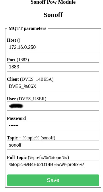
Without manual mqtt configuration the firmware tries to connect to the mqtt server using mDNS. I've never tried this feature so I don't know if it works or not, and don't know what happens when multiple MQTT servers are available, or when user/password is needed to connect.
With the configuration on the screenshot above you can subscribe to the topic and see what happens.
I'm using the following syntax as topic: sonoff/[MAC ADDRESS without colon]/%prpefix%
The prefix can be tele,state or cmnd.
Example subscribe:
Example outputs:1. sonoff/B4E62D14BE5A/tele/SENSOR {"Time":"2018-07-01T18:57:27","ENERGY":{"Total":2.262,"Yesterday":1.330,"Today":0.077,"Power":2,"Factor":0.05,"Voltage":222,"Current":0.146}}
2. sonoff/B4E62D14BE5A/tele/STATE {"Time":"2018-07-01T18:57:33","Uptime":"2T00:34:12","Vcc":3.142,"POWER":"ON","Wifi":{"AP":1,"SSId":"Vinyo-Net","RSSI":52,"APMac":"6C:3B:6B:A0:D2:79"}}
3. sonoff/B4E62D14BE5A/stat/POWER OFF
Explanation:
-
This is a Sonoff POW module which reports power usage. You can see that the message is in JSON format.
-
Tasmota firmware reports telemetry information (RSSI, Uptime, power state, etc.) periodically (in every 300s by default). This message is also in JSON format.
-
When you turn the relay on or off (even with the web interface or via MQTT message) the device reports the new state. In this particular situation I turned the device off using the web interface.
These three steps are essential to use your device with OpenHAB & MQTT. You can go through all web configuration elements/options, but this post doesn't aim to give you a complete guideline to Tasmota firmware.
3.4. Sending Commands To The Device Via MQTT
Before you start you can check all available commands on Tasmota GitHub page: https://github.com/arendst/Sonoff-Tasmota/wiki/Commands If you are planning to deal with Tasmota firmware I recommend you to bookmark this page, it is very helpful.
When you want to send commands to tasmota you always have to use the cmnd prefix.
Since we are speaking about relays, maybe the first question comes up: how to ON or OFF them.
Let's see the web page mentioned before (Commands):
In this first example I will explain all available options to make the configuration method as clear as possible.
So in a terminal tab I always subscribe to the device topic to see what happens.
Command: mosquitto_sub -v -h 172.16.0.250 -u ***** -P ***** -t 'sonoff/B4E62D14BE5A/#'
3.4.1. Check The State Of The Relay:
Command: mosquitto_pub -h 172.16.0.250 -u ****** -P ****** -t sonoff/B4E62D14BE5A/cmnd/power -n
On the "subscribe" tab you can see these messages:
sonoff/B4E62D14BE5A/cmnd/power (null)
sonoff/B4E62D14BE5A/stat/RESULT {"POWER":"ON"}
sonoff/B4E62D14BE5A/stat/POWER ON
If you have for example Sonoff Dual, or Sonoff 4ch you can specify which channel you want to use.
For example if you want to check the 3rd channel you can use this command:
mosquitto_pub -h 172.16.0.250 -u ****** -P ****** -t sonoff/B4E62D14BE5A/cmnd/power3 -n
I'm using a POW module for introduction, it has no 3rd channel so get "unknown" result:
If your device has only one channel do not use the number, so use only the "POWER" word instead of "POWER1". But in case of any multi-channels you have to use POWER1, POWER2, etc.
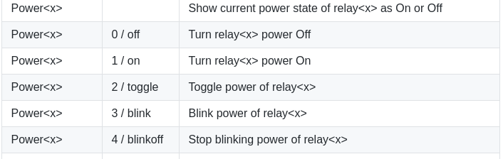
3.4.2. ON/OFF/TOGGLE The Relay
Regarding relays the most important activity is to turn on and off them.
Command:
mosquitto_pub -h 172.16.0.250 -u ****** -P ****** -t sonoff/B4E62D14BE5A/cmnd/power -m on
MQTT messages:
sonoff/B4E62D14BE5A/cmnd/power on
sonoff/B4E62D14BE5A/stat/RESULT {"POWER":"ON"}
sonoff/B4E62D14BE5A/stat/POWER ON
Command:
mosquitto_pub -h 172.16.0.250 -u vinyo -P Timike -t sonoff/B4E62D14BE5A/cmnd/power -m on
MQTT messages:
sonoff/B4E62D14BE5A/cmnd/power off
sonoff/B4E62D14BE5A/stat/RESULT {"POWER":"OFF"}
sonoff/B4E62D14BE5A/stat/POWER OFF
As you can see in the table you can use numbers instead of command, eg: 2 / toggle.
Let's fire the toggle command twice:
mosquitto_pub -h 172.16.0.250 -u ****** -P ****** -t sonoff/B4E62D14BE5A/cmnd/power -m 2
mosquitto_pub -h 172.16.0.250 -u ****** -P ****** -t sonoff/B4E62D14BE5A/cmnd/power -m 2
MQTT messages:
sonoff/B4E62D14BE5A/cmnd/power 2
sonoff/B4E62D14BE5A/stat/RESULT {"POWER":"OFF"}
sonoff/B4E62D14BE5A/stat/POWER OFF

sonoff/B4E62D14BE5A/cmnd/power 2
sonoff/B4E62D14BE5A/stat/RESULT {"POWER":"ON"}
sonoff/B4E62D14BE5A/stat/POWER ON
3.4.3. BLINK The Relay
This is an interesting feature of Tasmota FW. But first please check the following options related to blinking.
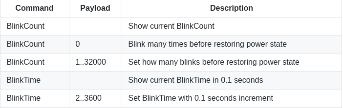
With this option the relay will turn on "BlinkCount" times for "BlinkTime" second*0.1.
Check the default settings using these commands:
mosquitto_pub -h 172.16.0.250 -u ****** -P ****** -t sonoff/B4E62D14BE5A/cmnd/BlinkCount -n
mosquitto_pub -h 172.16.0.250 -u ****** -P ****** -t sonoff/B4E62D14BE5A/cmnd/BlinkTime -n
MQTT messages:
sonoff/B4E62D14BE5A/cmnd/BlinkCount (null)
sonoff/B4E62D14BE5A/stat/RESULT {"BlinkCount":10}
sonoff/B4E62D14BE5A/cmnd/BlinkTime (null)
sonoff/B4E62D14BE5A/stat/RESULT {"BlinkTime":10}
If you connected a light to your relay, it will turn on for 1 second, 10 times. So, turn on for 1 sec, then turn off for 1 sec, turn on for 1 sec, turn on for 1 sec, and so on.
After turning on the relay ten times it remains OFF. But you can terminate blinking with "4/blinkoff" command.
Examples:
- Start Blinking:
mosquitto_pub -h 172.16.0.250 -u ****** -P ****** -t sonoff/B4E62D14BE5A/cmnd/power -m 3 - Terminate Blinking:
mosquitto_pub -h 172.16.0.250 -u ****** -P ****** -t sonoff/B4E62D14BE5A/cmnd/power -m 4
Maybe the missing feature of this equipment that you cannot configure BlinkCount and BlinkTime for each relays when use device with multiple channels.
In the rest of this configuration section I will show you some useful and exciting features of tasmota firmware.
3.4.4. Set Telemetry Period
If you need the status information of your device more frequently than its default (300s) you can configure the telemetry period with the following command:
After runing this command tasmota will publish "STATE" messages in every 30 seconds:
sonoff/B4E62D14BE5A/tele/STATE {"Time":"2018-07-01T20:53:09","Uptime":"2T02:29:48","Vcc":3.143,"POWER":"ON","Wifi":{"AP":1,"SSId":"Vinyo-Net","RSSI":58,"APMac":"6C:3B:6B:A0:D2:79"}}

sonoff/B4E62D14BE5A/tele/STATE {"Time":"2018-07-01T20:53:39","Uptime":"2T02:30:18","Vcc":3.143,"POWER":"ON","Wifi":{"AP":1,"SSId":"Vinyo-Net","RSSI":58,"APMac":"6C:3B:6B:A0:D2:79"}}
3.4.5. Set Timezone
Command:

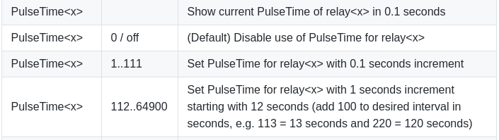
3.4.6. Set Pulse Time For Relay(s)
This feature is useful when you always want to turn off your relay after a certain time. Actually it is a simple timer. If you set up pulse time to 10 minutes, the relay will turn off after 10 minutes every time you turn it on.
I think these examples are far enough to understand how mqtt messages work, and after now that you know that you should be able to send your own commands to your device(s).
The next section aims to demonstrate how to use Tasmota firmware with OpenHAB.
4. OpenHAB Integration
So, I think this section will be the most interesting and useful part of this post. Since this post is about Tasmota firmware and its integration to OpenHAB I don't want to go deep inside the Mosquito install & setup and MQTT binding settings in OpenHAB. You can install and enable MQTT binding in PaperUI, and here is an example of mqtt.cfg.
mqtt:openhabPI.url=tcp://localhost:1883
mqtt:openhabPI.clientId=openhabPI
mqtt:openhabPI.user=*********
mqtt:openhabPI.pwd=*********
mqtt:openhabPI.retain=true
4.1. OpenHAB Items
As always first we need to set up the items.
4.1.1. Turn The Relay(s) On And Off Item(s)
My first example is for 1CH sonoff modules (S20, Basic, POW, etc).
Switch prod_sonoff_BCDDC28027AD_switch1        "Pantry Fan"                         <fan>    (sonoffsw,Sonoff)
    { mqtt=">[openhabPI:sonoff/BCDDC28027AD/cmnd/power1:command:*:default],
            <[openhabPI:sonoff/BCDDC28027AD/tele/STATE:state:JSONPATH($.POWER)],
            <[openhabPI:sonoff/BCDDC28027AD/stat/POWER:state:default]", autoupdate="true" }
The second example is for 4CH modules:
Switch prod_sonoff_6001949C6548_switch1         "SL-Right 1,3"                         <light>    (sonoffsw,Sonoff,SL_ALL,SL_RIGHT,SL_13,Lights)
   { mqtt=">[openhabPI:sonoff/6001949C6548/cmnd/power1:command:*:default],
           <[openhabPI:sonoff/6001949C6548/tele/STATE:state:JSONPATH($.POWER1)],
           <[openhabPI:sonoff/6001949C6548/stat/POWER1:state:default]", autoupdate="true" }

Switch prod_sonoff_6001949C6548_switch2         "SL-Right 2,4"                         <light>    (sonoffsw,Sonoff,SL_ALL,SL_RIGHT,SL_24,Lights)
   { mqtt=">[openhabPI:sonoff/6001949C6548/cmnd/power2:command:*:default],
           <[openhabPI:sonoff/6001949C6548/tele/STATE:state:JSONPATH($.POWER2)],
           <[openhabPI:sonoff/6001949C6548/stat/POWER2:state:default]", autoupdate="true" }

Switch prod_sonoff_6001949C6548_switch3         "SL-Left 1,3"                          <light>    (sonoffsw,Sonoff,SL_ALL,SL_LEFT,SL_13,Lights)
   { mqtt=">[openhabPI:sonoff/6001949C6548/cmnd/power3:command:*:default],
           <[openhabPI:sonoff/6001949C6548/tele/STATE:state:JSONPATH($.POWER3)],
           <[openhabPI:sonoff/6001949C6548/stat/POWER3:state:default]", autoupdate="true" }

Switch prod_sonoff_6001949C6548_switch4         "SL-Left 2,4"                          <light>    (sonoffsw,Sonoff,SL_ALL,SL_LEFT,SL_24,Lights)
   { mqtt=">[openhabPI:sonoff/6001949C6548/cmnd/power4:command:*:default],
           <[openhabPI:sonoff/6001949C6548/tele/STATE:state:JSONPATH($.POWER4)],
           <[openhabPI:sonoff/6001949C6548/stat/POWER4:state:default]", autoupdate="true" }
I try to explain my setup step by step. There are 3 mqtt settings, 1 inbound and 2 outbounds:
-
>[openhabPI:sonoff/BCDDC28027AD/cmnd/power1:command:*:default]
This is the outbound one. It's intended to control (turn on / off) the relay. When you turn the relay on / off in OpenHAB the proper command will be sent to the device.
Topic:sonoff/BCDDC28027AD/cmnd/power1
Type:command
Trgger:*
Transformation:default
When you turn ON/OFF the relay OpenHAB publish ON/OFF message tosonoff/6001949C6548/cmnd/power4topic. It is the same as described in 3.4.2. section:mosquitto_pub -h 172.16.0.250 -u ****** -P ****** -t sonoff/BCDDC28027AD/cmnd/power1 -m on -
<[openhabPI:sonoff/BCDDC28027AD/tele/STATE:state:JSONPATH($.POWER)]
With this you subscribe to thesonoff/BCDDC28027AD/tele/STATEtopic, and every time the sonoff device publish telemetry information the item's (relay) state will be updated to the actual state. -
<[openhabPI:sonoff/BCDDC28027AD/stat/POWER:state:default]
This is very similar to the previous one, this updates the state of this item (prod_sonoff_BCDDC28027AD_switch1).
Maybe you are wondering why I'm using two different mqtt topics to update the item state. The reason is very simple: I want to make sure that the item state is always the actual state of the relay. The telemetry (tele) topic is useful when you restart the OpenHAB and you don't have persistence set up for this item. In this case you lose the item state, but after the device posts its telemetry information the item state is updated. The second topic (stat) updates the item state immediately when you manually turn on/off the relay (with the button(s) on it). This configuration can be useful, when you control the relay via mosquitto_pub command, or using another application.
With these two inbound settings you can make sure that the item is always up-to-date.
There is an important thing to notice: the difference between 1ch and 4ch configuration:
1CH:
>[openhabPI:sonoff/BCDDC28027AD/cmnd/power1:command:*:default]
4CH:
>[openhabPI:sonoff/6001949C6548/cmnd/power1:command:*:default]
>[openhabPI:sonoff/6001949C6548/cmnd/power2:command:*:default]
>[openhabPI:sonoff/6001949C6548/cmnd/power3:command:*:default]
>[openhabPI:sonoff/6001949C6548/cmnd/power4:command:*:default]
power and even power1 with 1CH device, BUT in case of multi-channel device you have to use the appropriate channel number.
1CH:
<[openhabPI:sonoff/BCDDC28027AD/tele/STATE:state:JSONPATH($.POWER)]
4CH:
<[openhabPI:sonoff/6001949C6548/tele/STATE:state:JSONPATH($.POWER1)]
<[openhabPI:sonoff/6001949C6548/tele/STATE:state:JSONPATH($.POWER2)]
<[openhabPI:sonoff/6001949C6548/tele/STATE:state:JSONPATH($.POWER3)]
<[openhabPI:sonoff/6001949C6548/tele/STATE:state:JSONPATH($.POWER4)]
BUT!
When you configure telemetry topic subscription you can't use POWER1 for 1CH device, the right configuration is just the POWER without the number.
The situation is the same when you configure stat topic (sonoff/BCDDC28027AD/stat/POWER). The version without the number has to be used!
Of course, the multi-channel device configurations have to contain the number for each channel.
4.1.2. Telemetry Information
If you want to display information about your device you can use its telemetry topic. Example:
String prod_sonoff_6001949C6548_lwt            "S20A - Status [MAP(status_sonoff.map):%s]"  <lwt>         (g_slwt)    { mqtt="<[openhabPI:sonoff/6001949C6548/tele/LWT:state:default]", autoupdate="true" }

Number prod_sonoff_6001949C6548__RSSI          "RSSI [%d %%]"                               <signal>      (Sonoff)    { mqtt="<[openhabPI:sonoff/6001949C6548/tele/STATE:state:JSONPATH($.Wifi.RSSI)]" }

String prod_sonoff_6001949C6548_uptime         "Uptime [%s]"                                <timer>       (Sonoff)    { mqtt="<[openhabPI:sonoff/6001949C6548/tele/STATE:state:JSONPATH($.Uptime)]" }
JSON example (provided by the device):
{
   "Time":"2018-07-01T18:57:33",
   "Uptime":"2T00:34:12",
   "Vcc":3.142,
   "POWER":"ON",
   "Wifi":{
      "AP":1,
      "SSId":"Vinyo-Net",
      "RSSI":52,
      "APMac":"6C:3B:6B:A0:D2:79"
   }
}
If you have a bit experience with JSONs I think this configuration should be clear for you.
So if you need the WIFI RSSI value, the right configuration is: JSONPATH($.Wifi.RSSI)
Tasmota firmware provide LWT (Last Will Testament) with retain flag, so you can use it to show the device status (Active/Inactive/Unknown). The device is in UNKNOWN state when you restart OpenHAB and the LWT topic is not updated since the restart. Here is my transformation map for LWT:
Using persistence (not retain!) for LWT is a bit dangerous, because while the OpehHAB is offline, the state of the device may change, if so, after the OpenHAB becames online again, the last saved state will be displayed, not the actual one.4.1.3. Other Examples
This chapter is actually about more examples of displaying more information about your Sonoff device.
String prod_sonoff_6001949C6548_hostname       "Hostname [%s]"                              <info>        (Sonoff)    { mqtt="<[openhabPI:sonoff/6001949C6548/stat/STATUS5:state:JSONPATH($.StatusNET.Hostname)]", autoupdate="true"  }

String prod_sonoff_6001949C6548_BuildDateTime  "FW Build Date [%s]"                         <info>        (Sonoff)    { mqtt="<[openhabPI:sonoff/6001949C6548/stat/STATUS2:state:JSONPATH($.StatusFWR.BuildDateTime)]", autoupdate="true"  }

String prod_sonoff_6001949C6548_Vcc            "Vcc [%s]"                                   <info>        (Sonoff)    { mqtt="<[openhabPI:sonoff/6001949C6548/stat/STATUS11:state:JSONPATH($.StatusSTS.Vcc)]", autoupdate="true"  }

String prod_sonoff_6001949C6548_Time           "Time [%s]"                                  <info>        (Sonoff)    { mqtt="<[openhabPI:sonoff/6001949C6548/stat/STATUS11:state:JSONPATH($.StatusSTS.Time)]", autoupdate="true"  }

String prod_sonoff_6001949C6548_SSId           "SSId [%s]"                                  <info>        (Sonoff)    { mqtt="<[openhabPI:sonoff/6001949C6548/stat/STATUS11:state:JSONPATH($.StatusSTS.Wifi.SSId)]", autoupdate="true"  }

String prod_sonoff_6001949C6548_IPAddress      "IPAddress [%s]"                             <info>        (Sonoff)    { mqtt="<[openhabPI:sonoff/6001949C6548/stat/STATUS5:state:JSONPATH($.StatusNET.IPAddress)]", autoupdate="true"  }

String prod_sonoff_6001949C6548_Mac            "Mac [%s]"                                   <info>        (Sonoff)    { mqtt="<[openhabPI:sonoff/6001949C6548/stat/STATUS5:state:JSONPATH($.StatusNET.Mac)]", autoupdate="true"  }

String prod_sonoff_6001949C6548_Subnetmask     "Subnetmask [%s]"                            <info>        (Sonoff)    { mqtt="<[openhabPI:sonoff/6001949C6548/stat/STATUS5:state:JSONPATH($.StatusNET.Subnetmask)]", autoupdate="true"  }
OK. Haven't you noticed something? Look closer. :) That's it, the topics:
- sonoff/6001949C6548/stat/STATUS5
- sonoff/6001949C6548/stat/STATUS11
- sonoff/6001949C6548/stat/STATUS2
This information isn't posted automatically, or after a certain amount of time. In order to receive them you have to publish 0 to sonoff/6001949C6548/cmnd/STATUS topic.
You can try this with mosquitto_sub command:
sonoff/B4E62D14BE5A/stat/STATUS {"Status":{"Module":6,"FriendlyName":["Sonoff"],"Topic":"sonoff","ButtonTopic":"0","Power":1,"PowerOnState":1,"LedState":6,"SaveData":1,"SaveState":1,"ButtonRetain":0,"PowerRetain":0}}

sonoff/B4E62D14BE5A/stat/STATUS1 {"StatusPRM":{"Baudrate":115200,"GroupTopic":"sonoffs","OtaUrl":"http://sonoff.maddox.co.uk/tasmota/sonoff.bin","RestartReason":"Software/System restart","Uptime":"19T13:57:19","StartupUTC":"2018-07-11T03:38:44","Sleep":0,"BootCount":18,"SaveCount":171,"SaveAddress":"F9000"}}

sonoff/B4E62D14BE5A/stat/STATUS2 {"StatusFWR":{"Version":"5.14.0","BuildDateTime":"2018-05-15T15:29:54","Boot":31,"Core":"2_3_0","SDK":"1.5.3(aec24ac9)"}}

sonoff/B4E62D14BE5A/stat/STATUS3 {"StatusLOG":{"SerialLog":2,"WebLog":2,"SysLog":0,"LogHost":"","LogPort":514,"SSId":["Vinyo-Net",""],"TelePeriod":30,"SetOption":["00008009","55818000"]}}

sonoff/B4E62D14BE5A/stat/STATUS4 {"StatusMEM":{"ProgramSize":526,"Free":476,"Heap":19,"ProgramFlashSize":1024,"FlashSize":4096,"FlashMode":3}}

sonoff/B4E62D14BE5A/stat/STATUS5 {"StatusNET":{"Hostname":"sonoff_B4E62D14BE5A","IPAddress":"172.20.1.9","Gateway":"172.16.0.1","Subnetmask":"255.240.0.0","DNSServer":"172.16.0.1","Mac":"B4:E6:2D:14:BE:5A","Webserver":2,"WifiConfig":2}}

sonoff/B4E62D14BE5A/stat/STATUS6 {"StatusMQT":{"MqttHost":"172.16.0.250","MqttPort":1883,"MqttClientMask":"DVES_%06X","MqttClient":"DVES_14BE5A","MqttUser":"vinyo","MqttType":1,"MAX_PACKET_SIZE":1000,"KEEPALIVE":15}}

sonoff/B4E62D14BE5A/stat/STATUS7 {"StatusTIM":{"UTC":"Mon Jul 30 17:36:03 2018","Local":"Mon Jul 30 19:36:03 2018","StartDST":"Sun Mar 25 02:00:00 2018","EndDST":"Sun Oct 28 03:00:00 2018","Timezone":2,"Sunrise":"06:21","Sunset":"21:32"}}

sonoff/B4E62D14BE5A/stat/STATUS9 {"StatusPTH":{"PowerDelta":80,"PowerLow":0,"PowerHigh":0,"VoltageLow":0,"VoltageHigh":0,"CurrentLow":0,"CurrentHigh":0}}

sonoff/B4E62D14BE5A/stat/STATUS10 {"StatusSNS":{"Time":"2018-07-30T19:36:03","ENERGY":{"Total":40.988,"Yesterday":2.198,"Today":0.058,"Power":3,"Factor":0.09,"Voltage":220,"Current":0.161}}}

sonoff/B4E62D14BE5A/stat/STATUS11 {"StatusSTS":{"Time":"2018-07-30T19:36:03","Uptime":"19T13:57:19","Vcc":3.143,"POWER":"ON","Wifi":{"AP":1,"SSId":"Vinyo-Net","RSSI":52,"APMac":"6C:3B:6B:A0:D2:79"}}}
All these information can be displayed in OpenHAB if you want.
Only one thing left: as I mentioned before these topics aren't updated automatically, so you need a button for update them, but first an item must be created:
Switch prod_sonoff_6001949C6548_update "UpdateInfo" <update> (Sonoff) { mqtt=">[openhabPI:sonoff/6001949C6548/cmnd/STATUS:command:*:0]", autoupdate="false"}
0 to the device: command:*:0
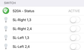
4.2. OpenHAB Sitemap
Now we have the items configured, but I think it would be useful to display them in the OpenHAB. :) To do that we have to configure our sitemap, as well.
Since this post is not an 'OpenHAB how to...', I will show you only one way to use the configured items.
4.2.1. Power Switches
Maybe the most useful step if I post the configuration of my 4CH device:
Frame label="Switches" {
Text item=prod_sonoff_6001949C6548_lwt
Switch item=prod_sonoff_6001949C6548_switch1 visibility=[prod_sonoff_6001949C6548_lwt=="Online"]
Switch item=prod_sonoff_6001949C6548_switch2 visibility=[prod_sonoff_6001949C6548_lwt=="Online"]
Switch item=prod_sonoff_6001949C6548_switch3 visibility=[prod_sonoff_6001949C6548_lwt=="Online"]
Switch item=prod_sonoff_6001949C6548_switch4 visibility=[prod_sonoff_6001949C6548_lwt=="Online"]
}
The only interesting thing in this configuration is the visibility part. Visibility configurations are intended to hide the switches when the device is not in "Online" state. You can skip this part, but I think it makes no sense to switch an unavailable device.
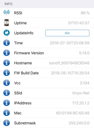
4.2.2. Display Information
Frame label="Info" {
Text item=prod_sonoff_6001949C6548__RSSI
Text item=prod_sonoff_6001949C6548_uptime

Switch item=prod_sonoff_6001949C6548_update mappings=[ON="Go!"]
Text item=prod_sonoff_6001949C6548_Time visibility=[prod_sonoff_6001949C6548_Time!="NULL"]
Text item=prod_sonoff_6001949C6548_fwver visibility=[prod_sonoff_6001949C6548_fwver!="NULL"]
Text item=prod_sonoff_6001949C6548_hostname visibility=[prod_sonoff_6001949C6548_fwver!="NULL"]
Text item=prod_sonoff_6001949C6548_BuildDateTime visibility=[prod_sonoff_6001949C6548_fwver!="NULL"]
Text item=prod_sonoff_6001949C6548_Vcc visibility=[prod_sonoff_6001949C6548_Vcc!="NULL"]
Text item=prod_sonoff_6001949C6548_SSId visibility=[prod_sonoff_6001949C6548_SSId!="NULL"]
Text item=prod_sonoff_6001949C6548_IPAddress visibility=[prod_sonoff_6001949C6548_IPAddress!="NULL"]
Text item=prod_sonoff_6001949C6548_Mac visibility=[prod_sonoff_6001949C6548_Mac!="NULL"]
Text item=prod_sonoff_6001949C6548_Subnetmask visibility=[prod_sonoff_6001949C6548_Subnetmask!="NULL"]
} // END : label="Info"
The RSSI and uptime values are posted with the telemetry information, so these are updated regularly. But the items after the Swtich item are updated only when you post 0 to the STATUS topic (Section: 4.1.3. Other Examples).
To make it much more understandable here is the item configuration again:
Switch prod_sonoff_6001949C6548_update "UpdateInfo" <update> (Sonoff) { mqtt=">[openhabPI:sonoff/6001949C6548/cmnd/STATUS:command:*:0]", autoupdate="false"}
And all these items are displayed only if they are not "NULL".
I hope it is clear. If you read this article carefully you can configure your own device.
Finally here are two screenshot about how it should look like:
5. Use Tasmota FW With Your Own Setup
And last but not least, this is my bonus chapter. :) What is this chapter about? Since Tasmota is an brilliant OpenSource software and Sonoff devices are base on ESP8266 OpenSource hardware you can build your own smart home switch.
You will need:
- ESP8266 module (ESP01, ESP07, NodeMCU devkit, etc).
- Relay (1CH, 2CH, etc) 5V
- 5V Power Supply
- 5V to 3V3 converter
- etc. :)
Please take a look at my 4CH setup in the beginning of this post for details. Of course you can create your own PCB, as well. :)
To customize Tasmota you will need an IDE (**I**ntegrated **D**evelopment **E**nvironment). If you do a google search for "compile tasmota" the first hit is exactly what we need. :) Beginner Guide Create your own Firmware Build So please forgive me, but I don't bother with a guide of "How to install and configure Atom", especially because it is only a few steps.
As I mentioned, some times, I'm not a developer so maybe my explanations are not always 100% right or clear, but always try to give you working solutions.
5.1. user_config.h
It this file you can pre-configure some values, most of them are configurable via the web interface.
Firstly, the most important thing is the Wifi set up. Why? Please, imagine the situation when you use an ESP01 and you used up all its GPIO port for switching relays. Why is it a problem? Because you don't have any GPIO pin left for a button, which is essential to put the device in Wifi config mode. You can pre-configure two different stations:
#define STA_SSID1              "My Wifi Station"
#define STA_PASS1              "UnbrakeablePassword"
#define STA_SSID2              ""
#define STA_PASS2              ""
If you scroll down a bit in the user_config.h, you can find the MQTT related settings. There is no reason to leave it blank. :)
Example:
#define MQTT_USE               1

#define MQTT_HOST              "172.16.0.250"
#define MQTT_FINGERPRINT1      "A5 02 FF 13 99 9F 8B 39 8E F1 83 4F 11 23 65 0B 32 36 FC 07"
#define MQTT_FINGERPRINT2      "A5 02 FF 13 99 9F 8B 39 8E F1 83 4F 11 23 65 0B 32 36 FC 07"
#define MQTT_PORT              1883
#define MQTT_USER              "userName"
#define MQTT_PASS              "Password"
Some other exciting options:
- NTP server:
- Time Zone:
-
Switch Mode:
-
MQTT retain:
-
And so on, and so on.... Please scroll down the file and configure everything you need.
- One more thing: In this file you have to configure which sensors you plan to use with your device, but do not select too many of them, because you can easily run into OOM exception.
5.2. sonoff_template.h
Here I had the feeling that I should know more about programming. :)
First create your own template. Example:
  { "Sonoff Custom",   // Sonoff Basic (ESP8266)
     GPIO_REL1_INV,    // GPIO00 Button
     GPIO_USER,        // GPIO01 Serial RXD and Optional sensor
     GPIO_REL2_INV,    // GPIO02
     GPIO_USER,        // GPIO03 Serial TXD and Optional sensor
     GPIO_USER,        // GPIO04 Optional sensor
     0,                // GPIO05
     GPIO_USER,        // GPIO06 (SD_CLK   Flash)
     0,                // GPIO07 (SD_DATA0 Flash QIO/DIO/DOUT)
     0,                // GPIO08 (SD_DATA1 Flash QIO/DIO/DOUT)
     0,                // GPIO09 (SD_DATA2 Flash QIO)
     0,                // GPIO10 (SD_DATA3 Flash QIO)
     0,                // GPIO11 (SD_CMD   Flash)
     0,                // GPIO12 Red Led and Relay (0 = Off, 1 = On)
     GPIO_LED1_INV,    // GPIO13 Green Led (0 = On, 1 = Off)
     GPIO_USER,        // GPIO14 Optional sensor
     0,                // GPIO15
     0,                // GPIO16
     0                 // ADC0 Analog input
  },
GPIO_REL1_INV,GPIO_REL2_INV.
Originally the GPIO0 was used to connect it with a button (I haven't modified the comment here on purpose for demonstration.)
What functionality can be used for the PINs? You can find all available functions here:
// User selectable GPIO functionality
enum UserSelectablePins {
  GPIO_NONE,           // Not used
  GPIO_DHT11,          // DHT11
  GPIO_DHT22,          // DHT21, DHT22, AM2301, AM2302, AM2321
...
...
  GPIO_REL1,           // Relays
  GPIO_REL2,
...
...
  GPIO_REL1_INV,
  GPIO_REL2_INV,
...
...
So what is the difference between GPIO_REL1 and GPIO_REL1_INV?
This configuration is related to NO (**N**ormally **O**pen) and NC (**N**ormally **C**losed) setup of the relay (if applicable).
Most relays have 3 connections: NC, NO, COM (common).
When you set the PIN to low:
- NC means that the circuit is closed.
- NO means that the circuit is open.
When you set the PIN to high the meanings of NC an NO are reverse.
So the usage of GPIO_REL1 and GPIO_REL1_INV depends on your hardware setup.
If you connect your stuff (which you want to turn OFF and ON) to NO you want to use the inverse version, because the relay will close the circuit when the PIN is put to low (0) state.
If you are using NC, you should choose the GPIO_REL1.
I hope this is clear for you, if not, give it a try. :)
There is special functionality which is the GPIO_USER. If you set a GPIO pin to this, you will be able to select its functionality on the web interface:

And where does the list come from?
// Text in webpage Module Parameters and commands GPIOS and GPIO
const char kSensorNames[] PROGMEM =
  D_SENSOR_NONE "|"
...
...
5.3. Example
Maybe it will be more clear if I show you an example. For demonstration I used a NodeMCU DevKit v0.9, 1CH 5V relay and a DHT22 sensor.
Hardware connections:
- DHT22
- VCC --> 3V3
- GND --> GND
- DATA --> D2
- Relay
- VCC --> 5V
- GND --> GND
- INPUT --> D3
To be able to choose the appropriate GPIO pins we have to know what D2 and D3 means.
 You can see in the picture that D1 is actually the GPIO5 and D2 is the GPIO4.
So the following modifications are needed in the sonoff_template.h file:
--- comp/Sonoff-Tasmota-development/sonoff/sonoff_template.h    2018-07-31 20:10:22.000000000 +0200
+++ Sonoff-Tasmota-development/sonoff/sonoff_template.h 2018-08-01 19:45:49.785921996 +0200
@@ -157,6 +157,7 @@
 // Supported hardware modules
 enum SupportedModules {
   SONOFF_BASIC,
+  BLOGTST,
   SONOFF_RF,
   SONOFF_SV,
   SONOFF_TH,
@@ -220,6 +221,7 @@

 const uint8_t kNiceList[MAXMODULE] PROGMEM = {
   SONOFF_BASIC,
+  BLOGTST,
   SONOFF_RF,
   SONOFF_TH,
   SONOFF_DUAL,
@@ -288,6 +290,26 @@
      0,                // GPIO16
      0                 // ADC0 Analog input
   },
+  { "Sonoff Blogtst", // Sonoff Basic (ESP8266)
+     GPIO_KEY1,        // GPIO00 Button
+     GPIO_USER,        // GPIO01 Serial RXD and Optional sensor
+     0,                // GPIO02
+     GPIO_USER,        // GPIO03 Serial TXD and Optional sensor
+     GPIO_DHT22,        // GPIO04 Optional sensor
+     GPIO_REL1,        // GPIO05
+     0,                // GPIO06 (SD_CLK   Flash)
+     0,                // GPIO07 (SD_DATA0 Flash QIO/DIO/DOUT)
+     0,                // GPIO08 (SD_DATA1 Flash QIO/DIO/DOUT)
+     0,                // GPIO09 (SD_DATA2 Flash QIO)
+     0,                // GPIO10 (SD_DATA3 Flash QIO)
+     0,                // GPIO11 (SD_CMD   Flash)
+     0,        // GPIO12 Red Led and Relay (0 = Off, 1 = On)
+     GPIO_LED1_INV,    // GPIO13 Green Led (0 = On, 1 = Off)
+     GPIO_USER,        // GPIO14 Optional sensor
+     0,                // GPIO15
+     0,                // GPIO16
+     0                 // ADC0 Analog input
+  },
   { "Sonoff RF",       // Sonoff RF (ESP8266)
      GPIO_KEY1,        // GPIO00 Button
      GPIO_USER,        // GPIO01 Serial RXD and Optional sensor
@@ -970,4 +992,4 @@

 */

-#endif  // _SONOFF_TEMPLATE_H_
\ No newline at end of file
+#endif  // _SONOFF_TEMPLATE_H_
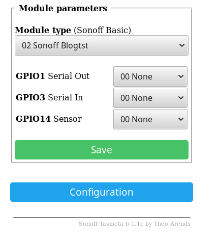
I defined a new template for my setup with "Sonoff Blogtst" name based on the "Sonoff Basic" module template. The following 3 lines were modified (GPIO04,05,12):
+     GPIO_DHT22,        // GPIO04 Optional sensor
+     GPIO_REL1,        // GPIO05
+     0,        // GPIO12 Red Led and Relay (0 = Off, 1 = On)
Important
If you define a completely new template you have to add two additional item to two different array: kNiceList, SupportedModules.
BLOGTST before SONOFF_BASIC in the kNiceList and SupportedModules arrays, as well.
You are almost done. Since the NodeMCU DevKit has "user" button we have two options:
- Configure the firmware to use this button. In this scenario you can use the user button to put the device to WiFi configuration mode. If you scroll back a bit to the picture about the pinout you can see that the button is connected to GPIO16. If you choose this option set the GPIO16 from
0toGPIO_KEY1. - Configure the WiFi parameters in the
user_config.h. To do this you should simply modify theSTA_SSID1andSTA_PASS1. Example:
To use DHCP (default) take a look at this line:--- comp/Sonoff-Tasmota-development/sonoff/user_config.h 2018-07-31 20:10:22.000000000 +0200 +++ Sonoff-Tasmota-development/sonoff/user_config.h 2018-08-01 19:34:45.629732934 +0200 @@ -59,8 +59,8 @@ #define WIFI_SUBNETMASK "255.255.255.0" // [IpAddress3] If not using DHCP set Network mask #define WIFI_DNS "192.168.2.27" // [IpAddress4] If not using DHCP set DNS IP address (might be equal to WIFI_GATEWAY) -#define STA_SSID1 "" // [Ssid1] Wifi SSID -#define STA_PASS1 "" // [Password1] Wifi password +#define STA_SSID1 "**********" // [Ssid1] Wifi SSID +#define STA_PASS1 "**********" // [Password1] Wifi password #define STA_SSID2 "" // [Ssid2] Optional alternate AP Wifi SSID #define STA_PASS2 "" // [Password2] Optional alternate AP Wifi password #define WIFI_CONFIG_TOOL WIFI_WAIT // [WifiConfig] Default tool if wifi fails to connect
Next steps: build! & upload. :) I've already written about uploading the firmware, but here is the example:
Open the web interface (configure module option) and select the newly configured template:
If everything is fine, after the reboot you should see the temperature and humidity values on the main page:

And, of course you can turn the relay on and off with the "Toggle" button.
In a nutshell this is how you can use Tasmota firmware with your own hardware setup in nutshell.
Maybe my explanations are not always the best, but I really hope this post is useful for you in case you want to work with Sonoff / Tasmota / OpenHAB or both of them... :) If you understand all these things I'm pretty sure you can build you own setup, even with custom hardware. I think at this time Sonoff+Tasmota is the cheapest solution to control equipment with OpenHab. Maybe with custom hardware setup could be cheaper but not much, and you should be aware of the time of assembling.